Atlas SY-777 terminal can be used to ring an attached bell according to schedules configured within the InfiniTime software. Refer to the Reader Configuration Table section of this document for more information on Bell Schedule Setup and Configuration. The following requirements below must be met for bells to operate with the InfiniTime Software.
InfiniTime Software Requirements
Bell usage requires purchase of the Bells Module. Contact your Inception Technologies Sales Representative for more information.
Bell Schedules must be configured for the reader. Refer to the ‘Reader Configuration Table – Bell Schedules’ section of this document for more information.
Bell Wiring: Hardware Components
Hardware requirements vary based upon the type of bell and wiring configuration desired. Many professionals with experience with electronics and electrical circuitry may wish to design a custom circuit to suit their environment and equipment. A basic custom wiring diagram is included for reference for professionals who wish to design their own circuitry. For users who are uncomfortable with designing their own circuitry Inception Technologies offers the SY-124 External Relay which can be used to safely isolate the hardware terminal from contact with the high voltage bell circuitry. An external power supply is required to provide power to the bell or buzzer. The SY777 terminal has dry relay contacts which simply close or open the circuit allowing current to pass when activated. The readers do not provide power to the relay contacts.
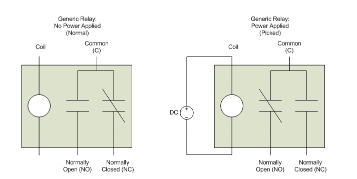
For those unfamiliar with the electrical parts contained in the diagrams below it is important to understand their basic operation before attempting to purchase and configure the equipment necessary to ring a bell with the InfiniTime Application. The central part used in the diagrams below is referred to as a relay. A relay can be thought of as an electrical switch. A coil of wire, a common contact, a normally closed (NC) contact, and a normally open (NO) contact are the four basic parts that comprise a relay. A diagram is shown below to illustrate the operation of a relay.

In the normal state, or when unpowered, the relay coil is not energized and the relay contacts are in their normal state. In the normal state the normally open contacts are open and the normally closed contacts are closed as the name suggests. When activated the coil becomes energized forming a magnetic field which causes the relay contacts to close or open respectively. This is referred to as the picked state where power is applied to the relay and the relay coil is energized. The relay will make a small clicking sound when it is picked. The relay contacts will switch their state, the normally open contact will be closed and the normally closed contact will be open. The contacts will remain in this position until power to the coil is removed at which point the contacts will revert to their normal state. The InfiniTime Application controls the duration for which the relay is picked. Generally when using a bell the wiring is setup in order to ring the bell when the relay is picked. The diagrams below provide example wiring circuits for bell control based upon the voltage and current requirements of the bell in use. Inception Technologies takes no responsibility for the wiring and setup of Bells and Access Control equipment. Customers attempting to wire their own access control without the assistance of a professional electrician do so at their own risk. Inception Technologies is not responsible for damage to equipment caused by improper wiring.
WARNING: The internal relay is rated to withstand a voltage range of 0 to 24V DC and a current load of up to 1A. Using an external power supply of more than 24 VDC will damage internal components of the Atlas SY-777 terminal. To prevent damage to the terminal, external bells should not draw more than 1A current. An external relay must be used to separate the clock from high voltage / current circuitry.
Bell Connection - High Voltage / Current Bells: Using SY-124

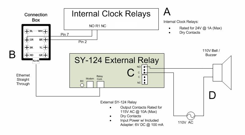
This diagram depicts the proper wiring of the SY-124 External Relay for use with a Bell or Buzzer. The SY-124 External relay is intended for those who do not wish to design their own circuitry for use with a bell or buzzer system. This diagram contains four major parts, the relay inside of the Atlast SY-777 terminal (A), A connection box used to simplify the wiring (B), The SY-124 Relay Contacts (C), and the Bell or Buzzer with power adapter (D).
It is important to keep in mind the electrical specifications for the Internal Relay (A) of the Atlas SY-777 terminal and its operation. When the bell is scheduled to ring the normally open relay contacts will close, completing the circuit and causing the SY-124 to pick the relay which makes the bell ring. The 6V DC power adapter provided with the SY-124 must be connected to the SY-124 and plugged in, as it provides the power necessary to energize the relay coils and pick the relay as explained in the previous section.
The connection box (B) is used to simplify the wiring between the SY-124 External Relay and the Internal Relay on the Atlas terminal. Connect a wire from the Normally Open Contact of Relay 1 within the SY-777 terminal to the Orange wire of the connection box. Similarly a wire must be connected from the Common Contact of Relay One to the Brown wire of the connection box. A straight through ethernet cable must be run from the RJ45 of the connection box to the Relay Control port of the SY-124. The orange wire is connected inside of the connection box to pin seven (7) of the straight through ethernet cable, while the brown wire is connected to pin two (2) of the straight through ethernet cable.
The SY-124 External Relay Contacts (C) provide the final connection between the Bell or Buzzer and a high voltage power source. It is important to keep in mind the electrical specifications for the External SY-124 Relay contacts when connecting a high voltage power source. The SY-124 Relay Contacts are rated for 115V AC at a current of 10A. The circuit connected to the contacts of the SY-124 should not exceed these voltage or current values. For your own safety, when wiring the bell and power source into the SY-124 ensure the AC power source of the bell and the DC power source of the SY-124 are turned off or unplugged. It will be necessary to remove the screws from the SY-124 and open the cover to expose the contact terminals. The contact terminals are of a screw down type, simply insert the wire into the slot of the connector and tighten the screw around the wire.
The Bell and AC Power Source assembly (D) are the final parts of the assembly. The power source should be placed in a safe and dry location. The buzzer may be placed appropriately within your facility.
Bell Connection - High Voltage / Current Bells: Custom Wiring

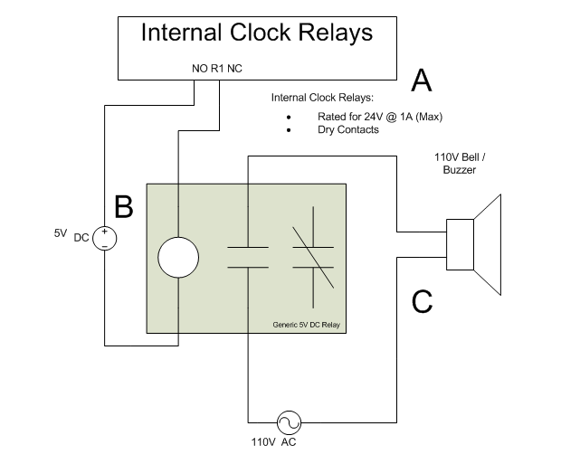
This diagram depicts an example of custom wiring for use with a Bell or Buzzer. This diagram contains three major parts, the relay inside of the Atlas terminal (A), a DC power supply (B), and the Bell or Buzzer with power adapter (C).
It is important to keep in mind the electrical specifications for the Internal Relay (A) of the Atlas terminal and its operation. When the bell is scheduled to ring the normally open relay contacts will close, completing the circuit and causing the DC power supply to pick the relay which makes the bell ring. The 5V DC power adapter must be plugged in as it provides the power necessary to energize the relay coils and pick the relay as explained in the previous section.
The 5V DC power adapter (B) should be connected directly to one end of the relay coil and the Normally Open Contact of Relay 1 within the Atlas terminal. The Common Contact of Relay 1 within the Atlas terminal must also be connected to the other side of the relay coil. In this way the relay coil will energize when the circuit is closed by the Atlas terminal at the appointed time.
The Relay Contacts (C) provide the final connection between the Bell or Buzzer and a high voltage power source. It is important to keep in mind the electrical specifications for the Relay contacts when connecting a high voltage power source. The voltage and current rating of the relay contacts are dependant upon the relay's construction and model. Refer to the data sheet provided by the relay's manufacturer for this information. The circuit connected to the contacts of the SY-124 should not exceed these voltage or current values. For your own safety, when wiring the bell and power source into the relay contacts ensure the AC power source of the bell and the DC power source used to energize the relay coil are turned off or unplugged. Standard procedure and safety guidelines dictate that all high voltage wiring must be safely enclosed. All measure must be taken to prevent inadvertent contact with an individual. Inception Technologies is not responsibile for any damages or injuries incurred while attempting to design and wire customized circuitry for these devices. It is recommended a professional electrician perform these tasks.
Bell Wiring Troubleshooting Procedure
Basic troubleshooting steps and failure points are listed below for the diagrams above.
If the bell does not ring as expected first test the wiring at the Internal Relays by shorting the wires connected to the Normally Open and Common contacts of the SY-777 internal relay together. Ensure all power supplies are plugged in or turned on. The bell should ring. If the bell does not ring check the following items:
Custom Wiring Diagram:
Ensure the DC Power source is connected properly and functioning.
Ensure the AC Power source is connected properly and functioning.
Ensure the AC Power source and Bell are connected to the proper relay contacts and to each other. The one side of the AC power source should be connected to the Normally Open contact while the other is connected to a contact on the bell or buzzer. The second contact of the bell or buzzer should be connected to the common contact of the relay.
SY-124 Diagram:
Ensure the DC Power adapter is connected to the SY-124 properly and plugged in. The Red Power LED should illuminate.
Ensure the AC Power source is connected properly and functioning.
Ensure the Normally Open (NO) Contact of the Internal SY-777 relay is connected to the orange wire of the connection box.
Ensure the Common (R1) contact of the Internal SY-777 relay is connected to the brown wire of the connection box.
Ensure a straight through ethernet cable is used between the connection box and the SY-124. If possible, test the cable with a cable tester or replace the cable.
Ensure the AC Power source and Bell are connected to the proper relay contacts and to each other. The one side of the AC power source should be connected to the Normally Open contact while the other is connected to a contact on the bell or buzzer. The second contact of the bell or buzzer should be connected to the common contact of the relay.